
This installation overview will be published in multiple parts due to the size. Please check back frequently, or subscribe to the blog, for additional posts.
Arrival and initial inspection
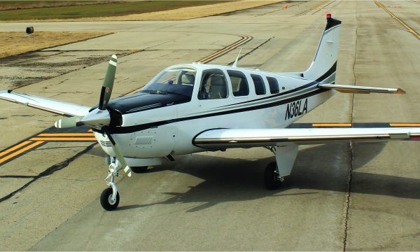
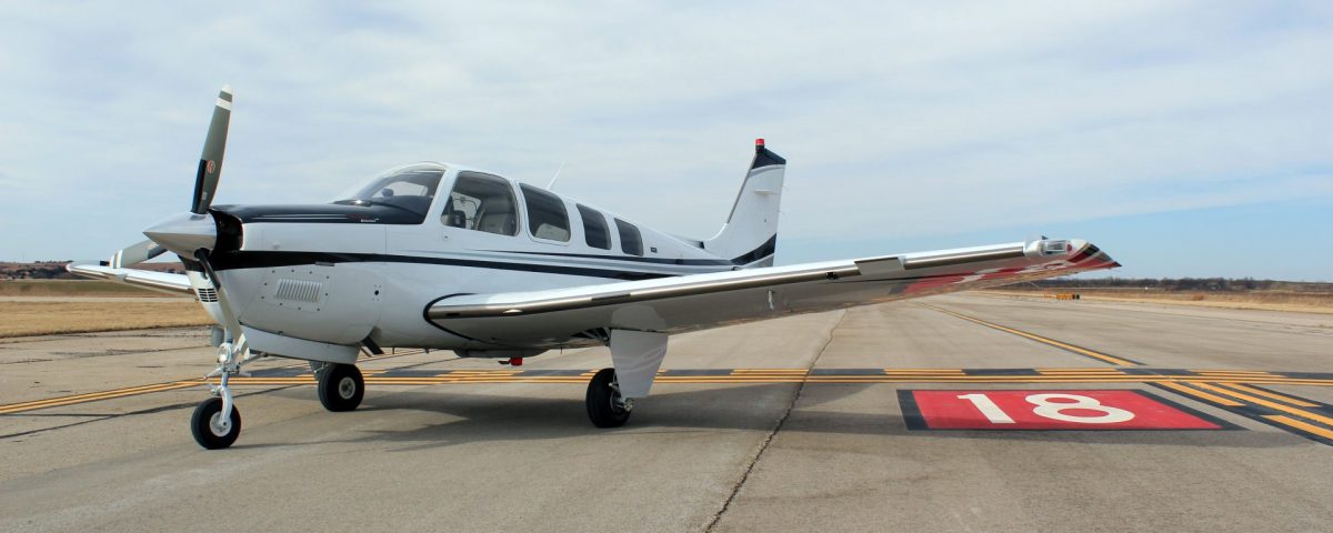
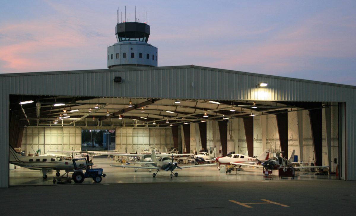
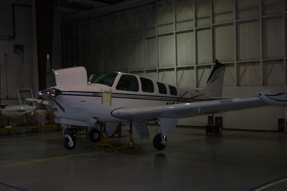
Upon arrival at KSLN an aircraft will typically be met by a representative of CAV Aerospace and immediately pulled into the hangar.
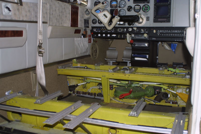
An inspection will be conducted to ensure the aircraft is compatible with the STC to be installed and that any deficiencies are noted for the safety of our installation personnel and pilots. After inspection the aircraft is opened up and the interior is removed to allow installation of internal components and routing of plumbing / electrical wiring through the cabin.
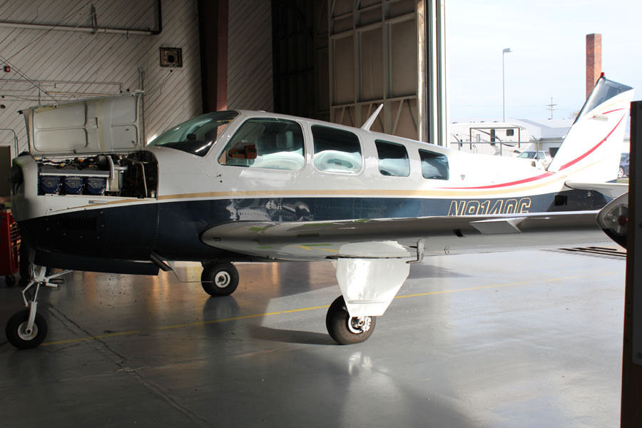
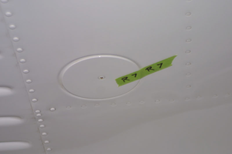
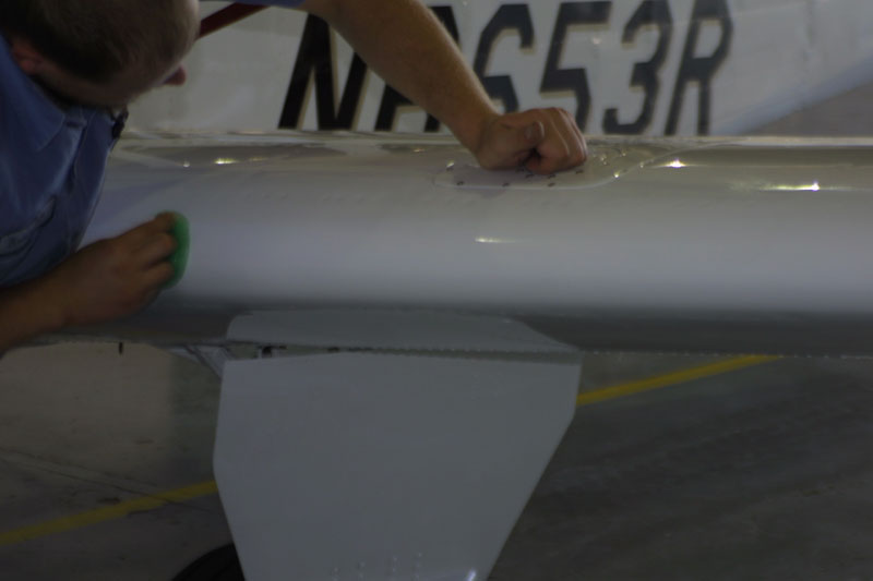
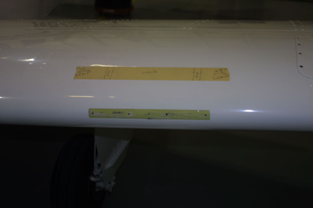
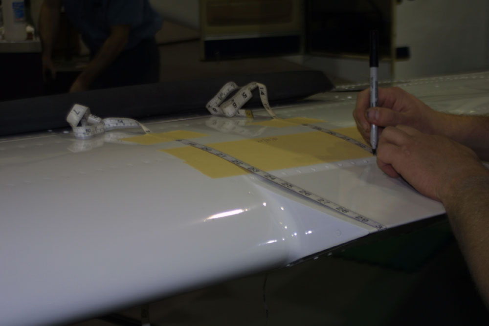
The aircraft’s flight surfaces are prepared for the installation. This includes marking and removing all access doors, marking and removing all stall strips and the removal of the “wedges”, the large vortex generators found on 1984 or newer 36 models.
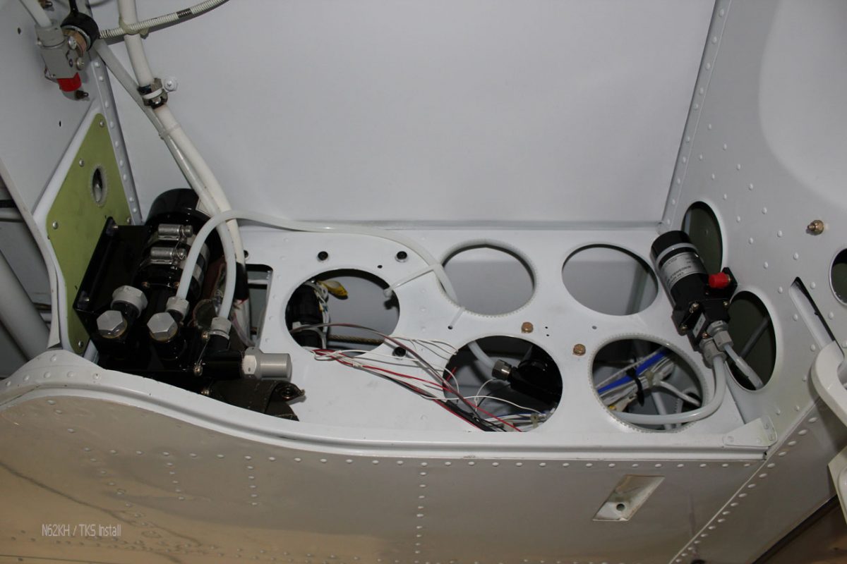
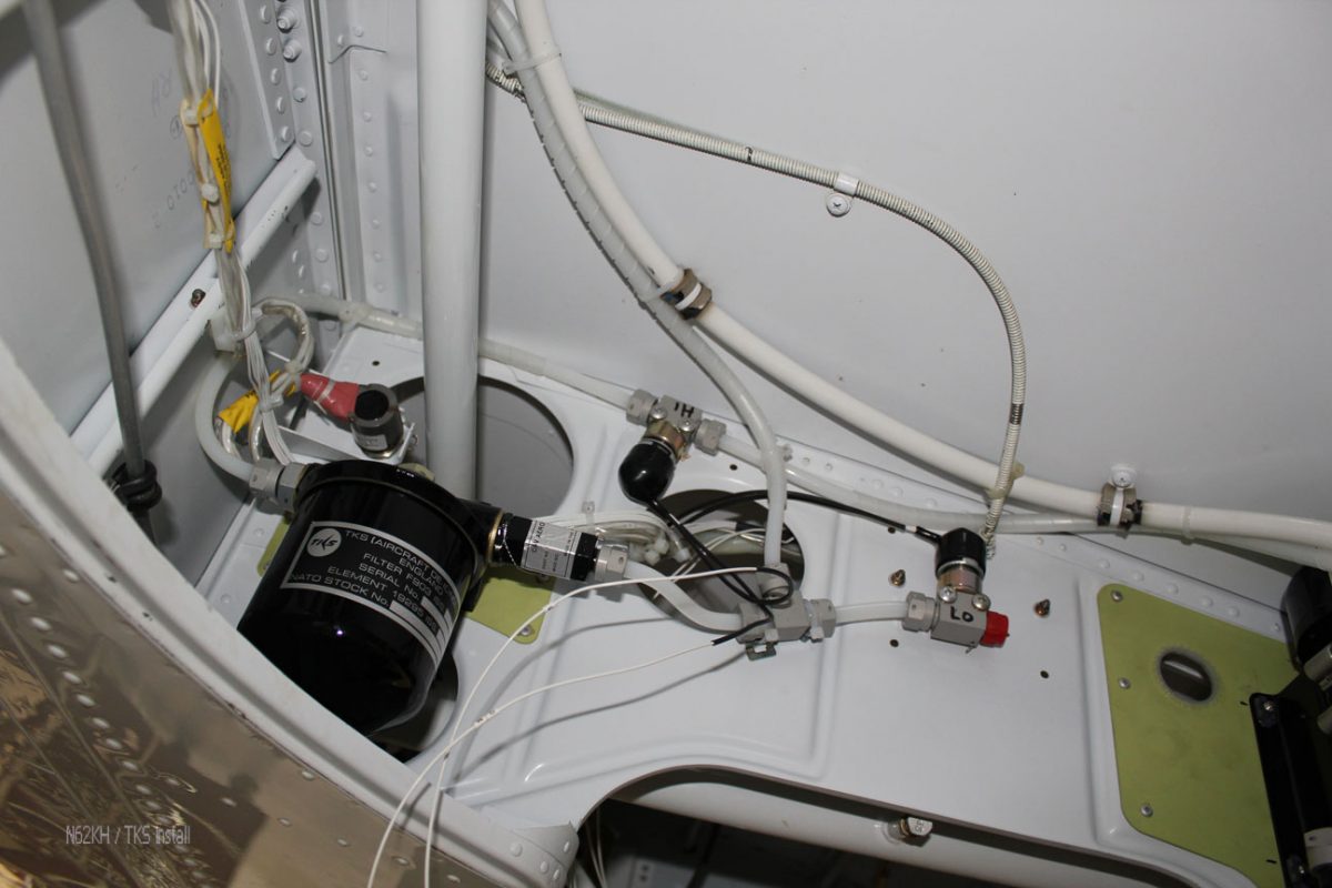
While the preparations are made on the flight surfaces another installation technician will be conducting the component installation in the right wheel well. Components installed in the wheel well include the TKS main pump, the windshield pump, a solenoid, a high pressure switch, a low pressure switch and a filter.
The propeller is pulled to allow installation of the TKS slinger ring. The prop is moved to a dedicated room where the temperature and humidity is kept at optimal levels for the bonding agent’s cure requirements.
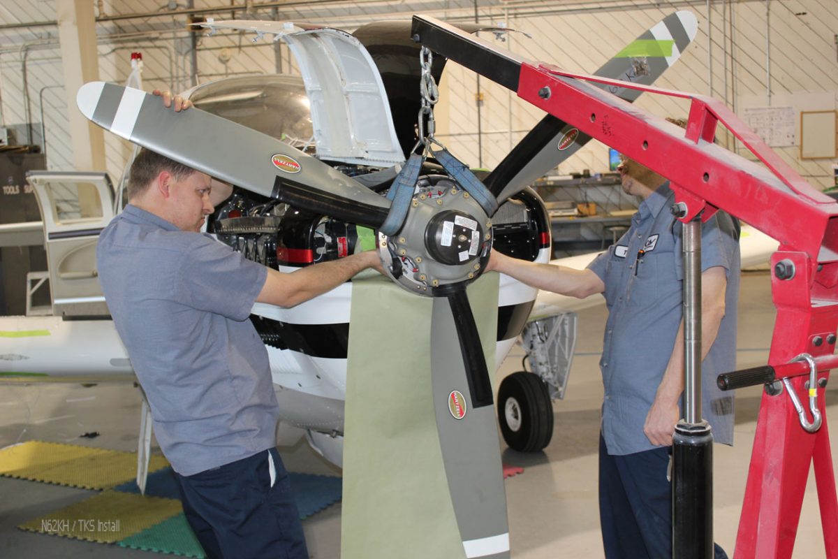
When an aircraft comes to us with a heated prop, as in the picture above, we remove the heated elements, contact ring and brush as these items occupy the exact same space required for the TKS slinger. The slinger ring not only keeps the prop blades protected from ice but has an added benefit of helping protect the rest of the airframe through fluid departing the blades.
Part 2 of the Bonanza TKS installation can be found here.
Related News
J.A. Air Center Newest TKS Installation Center
3rd July 2016