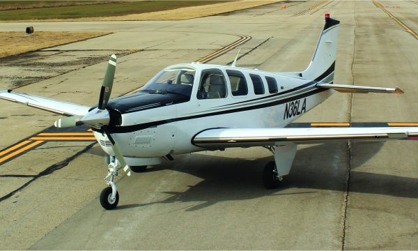
With the plumbing and electrical wiring run, the installation moves to the windshield spraybar, the ice detection light and the prop.
The Windshield Spraybar Assembly
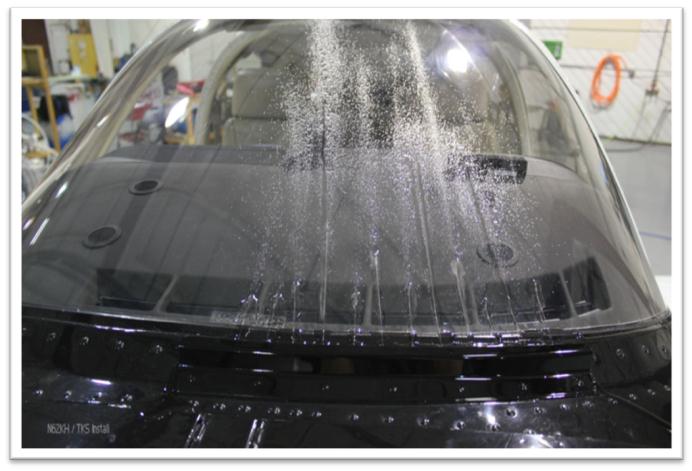
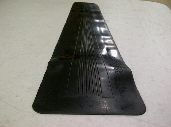
The windshield spraybar on the Bonanza is installed in front of the left side windscreen. The spraybar itself is a stainless steel tube with 12 holes drilled to jet TKS fluid onto the windscreen. The spraybar is bent to follow the rivet line of the lower windscreen.
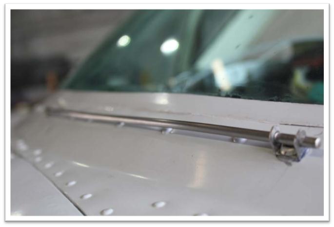
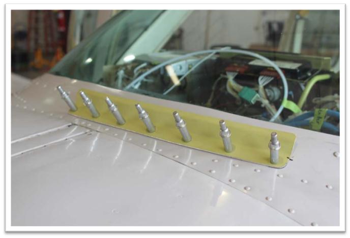
A deflector is riveted over the spraybar to ensure the fluid flows properly in flight.
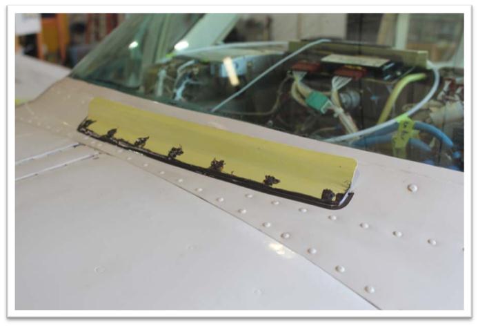
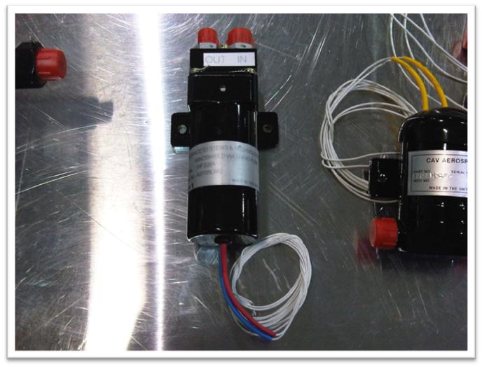
The windshield spraybar is not running when the rest of the TKS system is active. The spraybar has its own dedicated pump. When the spraybar is activated from the control panel, the fluid will spray for 4 seconds and stop automatically. After a 4 second delay, the spraybar may be activated again if necessary.
The Ice Detection Light Assembly
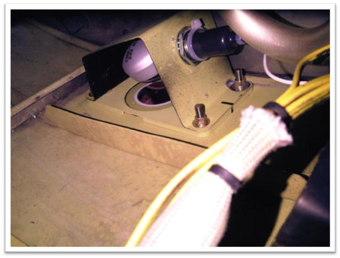
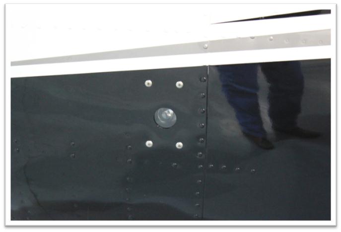
The ice detection light is installed in the lower left cowling in order to allow illumination of the left wing. The ice detection light bracket holds a light bulb which is angled to the middle section of the leading edge of the wing.
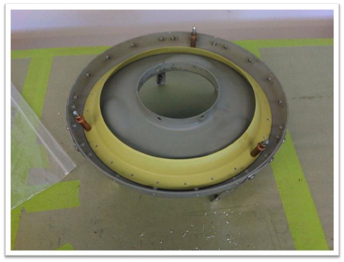
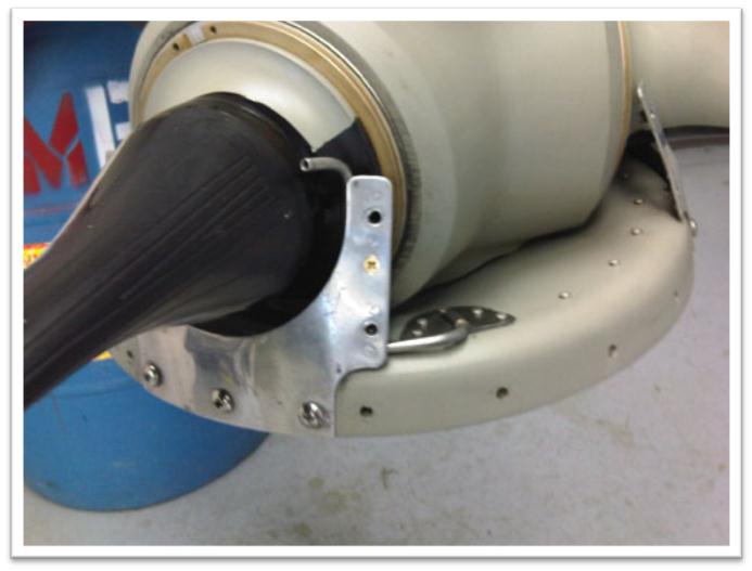
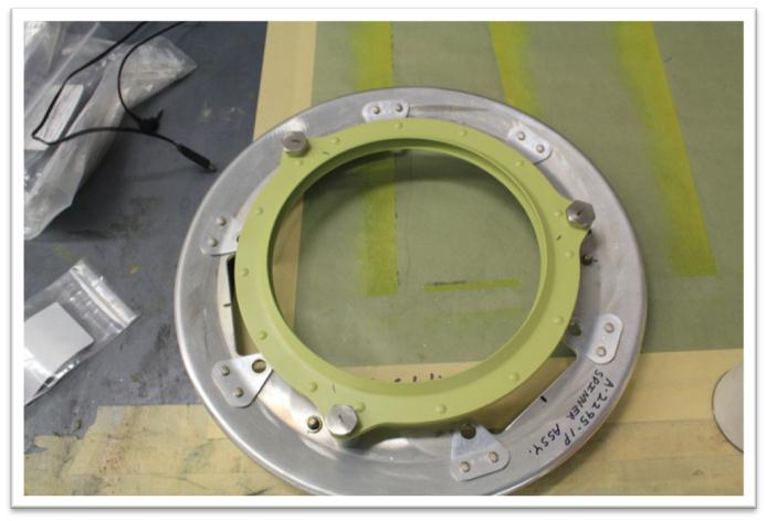
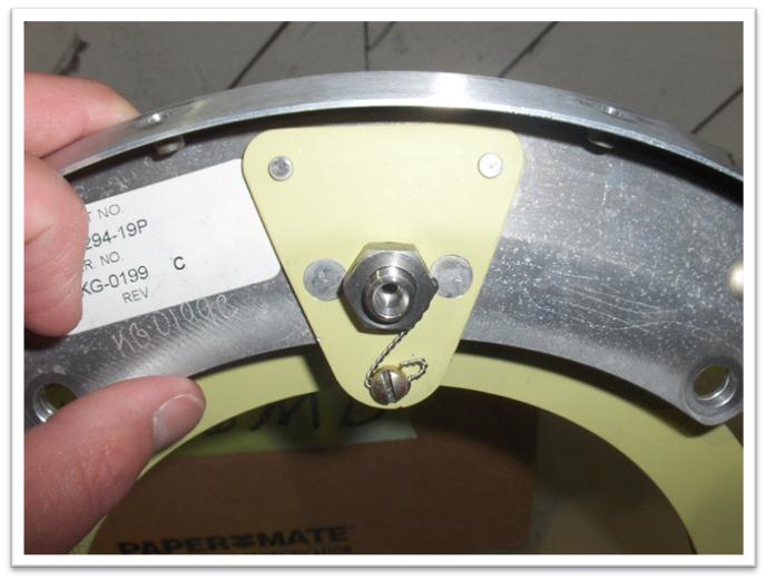
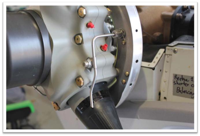
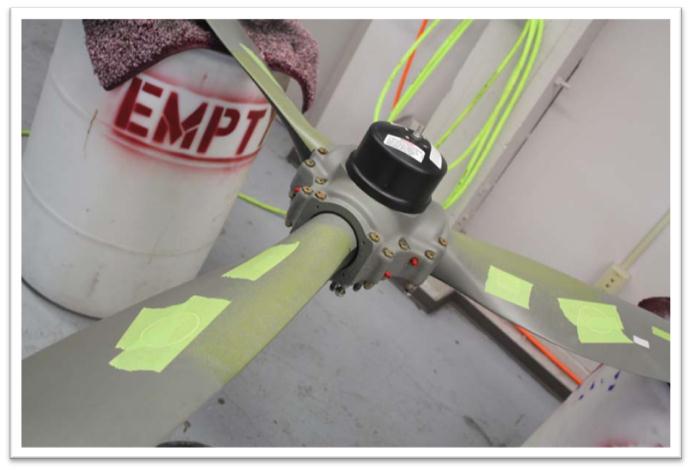
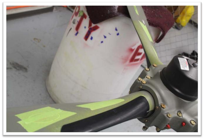
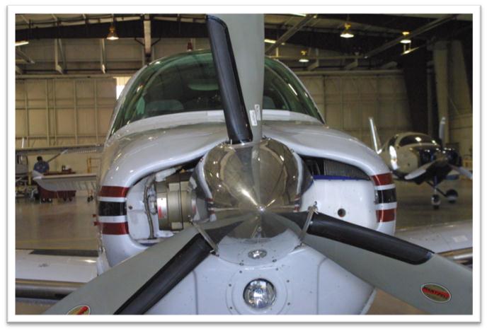
The TKS Slinger Ring Assembly
A predetermined flow of TKS ice-protection fluid is metered into a propeller slinger ring through an injection nozzle. Once the fluid enters the slinger ring, centrifugal force directs the fluid to the outermost portion of the ring. Holes mounted in the slinger ring provide a path for the fluid to travel, ultimately coming out of a tube positioned on the leading edge of the propeller. The propeller blade leading edges are fitted with a channeled boot, providing a flow path for the TKS fluid. The fluid passes out of the feed tube and onto the ribbed boot. Centrifugal force directs the fluid outward.
The manufacturer of the prop will determine the build of slinger required.
A McCauley prop will have a slinger ring which is bonded to the prop hub. Scoops mounted in the slinger pick up the fluid and deliver it to the prop blades.
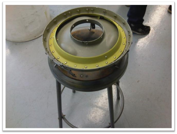
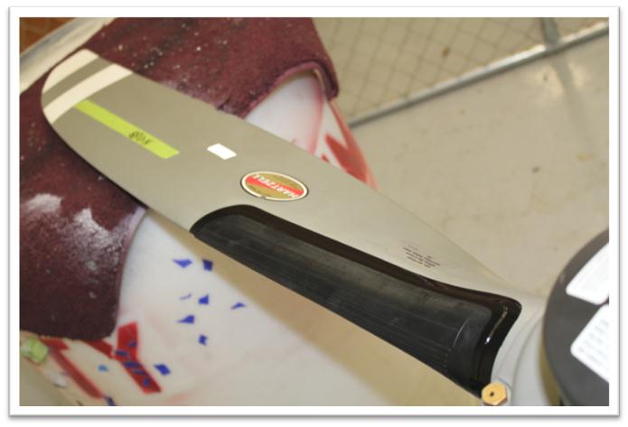
A Hartzell prop will have a slinger ring which is mounted in a stand-off position. Three hollow bolts are used to mount the slinger to the prop hub. The bolts pick up the fluid and deliver it to the prop blades.
MT manufactured props must have a MT manufactured slinger ring installed.
McCauley
Hartzell
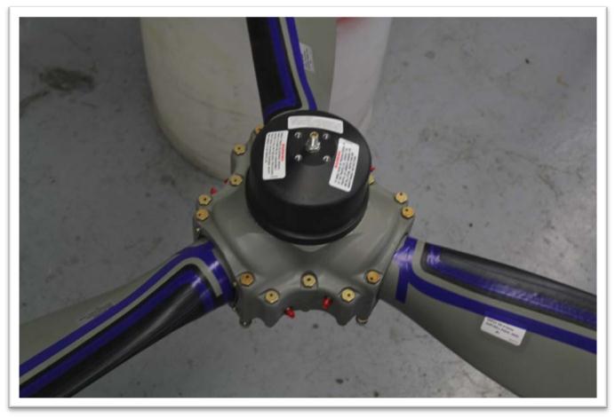
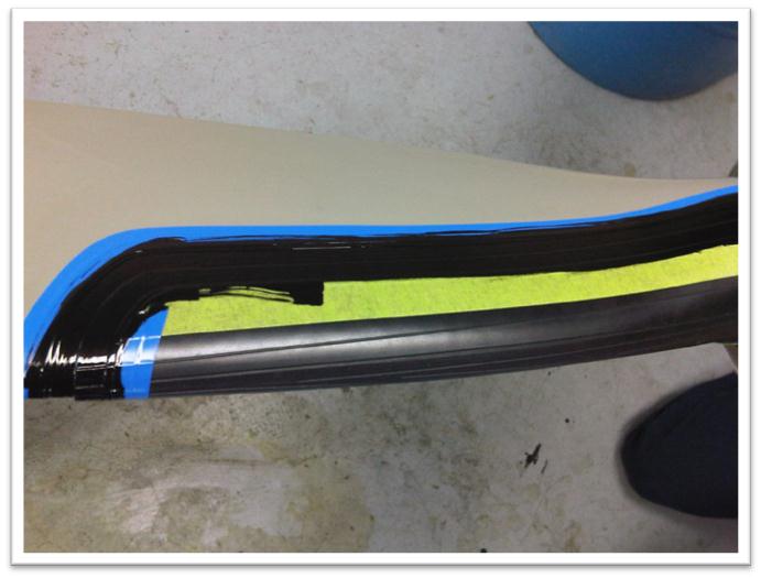
The propeller blades
After the propeller has been removed from the aircraft and placed in the prop shop, the prop blades are prepared for the TKS boot installation. If the aircraft was previously equipped with thermal propeller protection, the heated boot elements and all adhesive residues are removed. The prop blades are then cleaned and the area where the TKS boots will be installed is prepared.
The prop will be dynamically balanced after system testing is completed.
Related News
J.A. Air Center Newest TKS Installation Center
3rd July 2016